


Alstom P40 Agile P14DA Agile Numerical Feeder Protection relay (W:102.4mm X H:177.0mm D:185.6mm)
SKU : P40-Agile-P14DA-P14DA11E1B0
Mfr Part No. : P14DA11E1B0
HSN Code : 8536
ALSTOM P14DA (Protocol Available:- Modbus / IEC103 )
ALSTOM P14DA (Protocol Available:- Modbus / IEC103 )
| Description | Price / Qty |
Total |
|---|---|---|
|
Alstom P40 Agile P14DA Agile Numerical Feeder Protection relay (W:102.4mm X H:177.0mm D:185.6mm)
SKU Code
:
P40-Agile-P14DA-P14DA11E1B0
Mfr Part No.:P14DA11E1B0
|
₹ 0
Pieces
|
₹ 0 |
|
Alstom P40 Agile P14DA Agile Numerical Feeder Protection relay (W:102.4mm X H:177.0mm D:185.6mm)
SKU Code
:
P40-Agile-P14DA-P14DA11A2B0
Mfr Part No.:P14DA11A2B0
|
₹ 0
Pieces
|
₹ 0 |
The P14N non-directional feeder, P14D directional feeder and P94V voltage and frequency IEDs bring the design rigour and technology of transmission applications to the entire utility and industrial market. The footprints of both the device physical size and the lifecycle environmental impact have been minimised using state-of-the-art design, component, and process selection. Agile solutions from GE are ideal for new-build and retrofit alike.
Agility and Versatility
MiCOM P40 Agile IEDs provide an integrated solution for the complete protection, control and monitoring of electrical power systems. Application for overhead lines, underground cables, busbars, breakers, transformers, reactors and distributed generation is supported, right from distribution (as primary protection) to transmission voltage levels (as back-up). The IEDs are suitable for a wide variety of applications in solidly-earthed, resistance-earthed and Petersen coil systems alike.
Key Benefits
- Comprehensive current, voltage, power and frequency protection
- Multi-stage independent protection elements
- Two stage circuit breaker failure and breaker condition monitoring
- Switchgear supervision including CT/VT, DC supply, full trip circuit supervision
- Support for multiple industry standard communication protocols including IEC 61850
- Compact, withdrawable design with 4”, 6”, and 8” case sizes for reduced space applications
Key Features
- Comprehensive current, voltage, power and frequency protection functions
- Multi-stage independent protection elements, variety of curves in 4 setting groups
- High Impedance Fault, Load Encroachment, Switch onto fault and Fault Locator
- Rate of change, full-scheme auto-reclose, TEFD and synchrocheck
Protection & Control
The P14N non-directional feeder, P14D directional feeder and P94V voltage and frequency IEDs bring the design rigor and technology of transmission applications to the entire utility and industrial market. P40 Agile IEDs provide an integrated solution for the complete protection, control and monitoring of electrical power systems. Application for overhead lines, underground cables, busbars, breakers, transformers, reactors and distributed generation is supported, right from distribution (as primary protection) to transmission voltage levels (as back-up). The IEDs are suitable for a wide variety of applications in solidly-earthed, resistance- earthed and Petersen coil systems alike.
Powerful graphical logic allows the user to customise the protection and control functions. It is also used to program the optically isolated inputs, relay outputs and LEDs. The logic includes OR, AND and majority gates, timers, and set/reset latch functions, with the ability to invert the inputs and outputs, and provide feedback. The relay has 32 PSL timers could be conveniently configured in PSL, setting or from the relay front panel. The PSL imposes no delay on logic throughput, using concurrent processing being used instead of sequential equations and avoiding any logic ‘race’ issues.
P14D Functional Block Diagram
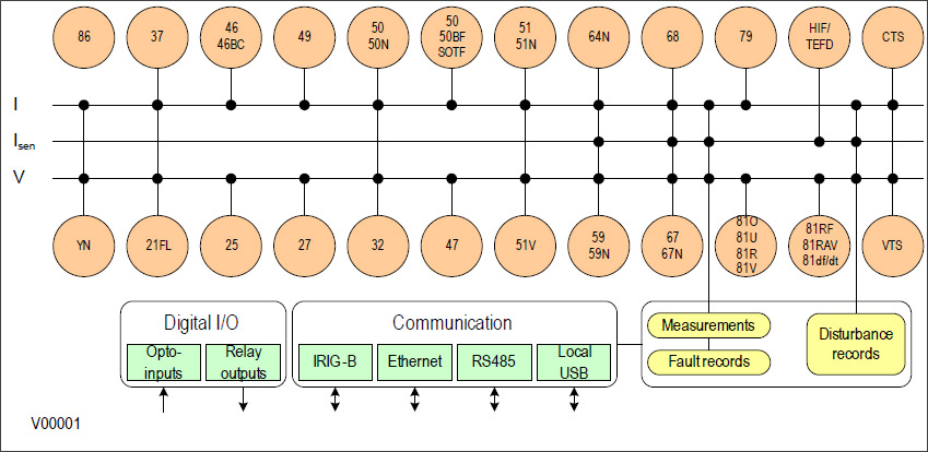
-
Agile P14N, P14D, P94V
 Agile P14N, P14D, P94V
Advanced Communications
Two communication ports are standard: a rear port providing remote communications and a front port for substation staff. The front USB port allows the programming of settings, configuration of the programmable scheme logic, extraction and viewing of event, disturbance and fault records, viewing of measurements and the instigation of control functions.
Supported Protocols:
- Courier / K-Bus
- Modbus
- IEC 60870-5-103
- DNP 3.0 (RS485 serial or Ethernet)
- IEC 61850 (100 Mbit/s Ethernet)
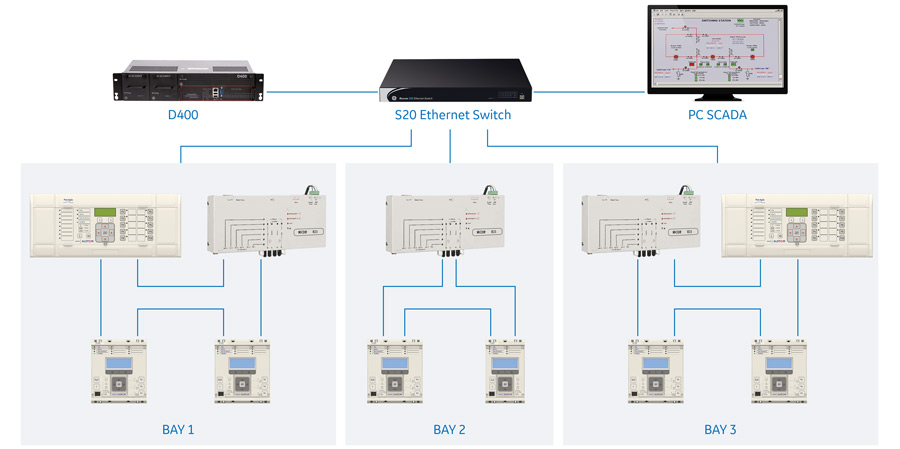
IEC 61850 or DNP 3.0 over Ethernet are available when the optional Ethernet port is ordered in 30TE and 40TE models. Redundant Ethernet protocol PRP, HSR and RSTP are also available in dual RJ45 or dual fiber. The copper physical link option uses RJ45 connectors, the fiber option uses LC connectors. IEC 61850 offers high-speed data exchange, peer-to- peer communication, reporting, disturbance record extraction and time synchronisation. To help smooth transition from the existing protocol to the IEC 61850 protocol, the P40 Agile relay had been designed to provide concurrent Courier, Modbus or DNP3 on the RS485 while provide IEC 61850 over Ethernet port.
MiCOM P40 Agile offers 64 virtual inputs, and best-in-class GOOSE performance. An optional second rear Courier port is available, designed typically for local engineering workstation access, or for modem access when the main port is reserved for SCADA.
MiCOM P40 Agile Advanced Communications Network
Key Features
- Comprehensive metering & power-up diagnostics
- Two stage circuit breaker failure and breaker condition monitoring
- Switchgear supervision including CT/VT, DC supply, full Trip Circuit Supervision, CB failure
- Switch control and status (up to 8) and up to 2048 events and 10.5 s disturbance records
Metering, Monitoring & Diagnostics
All events, fault and disturbance records are time tagged to a resolution of 1 ms. Up to 2048 time-tagged event records are stored in the flash memory and can be extracted using the communication ports or viewed on the front panel display.
Records of the last 10 faults are stored in the flash memory. Fault data is also available via IEC 61850 protocol. The internal disturbance recorder has up to 9 analogue channels, 64 digital channels and 1 time channel. The memory capacity is approx. 50 records for a typical 0.5 s duration.
The measurements provided, which may be viewed in primary or secondary values, can be accessed via the front panel LCD display, or the communications ports. Measurements are available in P14D for easy retrofit of KMPC130 devices.
P40 Agile can be used to monitor the integrity of the breaker coils and circuits with support for various TCS schemes.
MiCOM S1 Agile Software Toolsuite
- Configuration file creation and management, following the substation topology
- Ethernet and IEC 61850 configuration, including SCL import and export
- Programmable logic, menu text and IDMT curve profiles
- Setting conversion to the new P40 Agile IEDs.
- Events and disturbance record extraction and viewing
- Embedded product selector
- Full successor to Micom S1
- Zero or minimal training to move from S1 Studio to S1 Agile
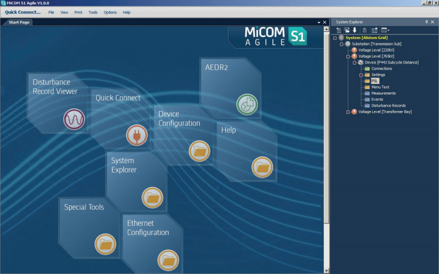
S1 Agile is the truly universal IED engineering toolsuite. No-longer are separate tools required for redundant Ethernet configuration, scheme operational dashboards, programmable curve profiles or automatic disturbance record extraction – all applications are embedded.
MiCOM S1 Agile Universal IED Engineering Toolsuite
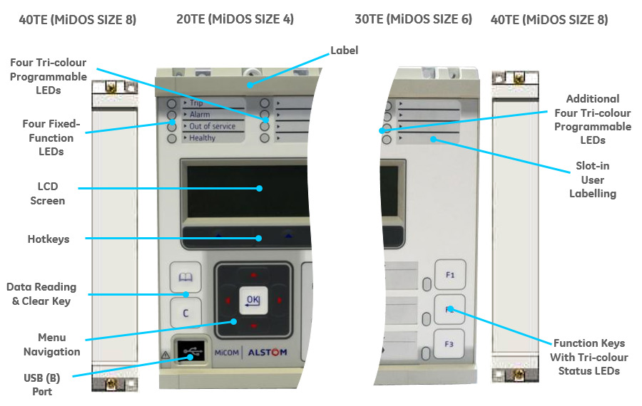
Flexible Hardware Platform
- Space-saving 4U height and 20TE (4"), 30TE (6") or 40TE (8") case sizes
- A front USB port and a rear RS485 port
- Power-up diagnostics and continuous self-monitoring
- Wide choice of opto-isolated binary inputs and output relays
- N/O (form A) and N/C (form B) watchdog contacts
- Field upgradeable to change the relay model avoiding costly hardware change via firmware upgrade
The front-panel interface allows direct IED interaction. A USB front port offers enhanced access by laptop computers. Integrated user function keys and tri-color programmable LEDs provide a cost-effective solution for control and annunciation. Numerous, optional, modern communication protocols, including IEC 61850, ensure interfacing to upper-level Supervisory, Control, Automation or Data Acquisition systems.
Intuitive Front Panel Interface
MiCOM P40 Agile Functions
| FUNCTION | P14NB | P14NZ | P14DB | P14DG | P14DL | P14DZ | P94VB | P94VP | P94VR | P14DH | P14DA |
|---|---|---|---|---|---|---|---|---|---|---|---|
| NON-DIRECTIONAL | DIRECTIONAL | VOLTAGE & FREQUENCY | DIRECTIONAL | ||||||||
| Trip circuit supervision (H7 scheme) |
Option |
||||||||||
| Rear communication port (software selectable to convert into demodulated (RIG-B) |
RS485 |
RS485 |
RS485 |
RS485 |
RS485 |
RS485 |
RS485 |
RS485 |
RS485 |
RS485 |
RS485 |
| 2nd Rear Communications port options |
RS485, FO, RJ45, dual FO or dual RJ45 Ethernet* |
- |
|||||||||
| Communication protocols |
IEC-103, IEC 61850, Modbus, Courier, DNP3, or DNP3 Ethernet |
IEC-103, Modbus, Courier or DNP3 | |||||||||
| Digital inputs min./ max.hardware options |
3 / 13 |
3 / 13 |
6 / 13 |
6 / 13 |
6 / 13 |
6 / 13 |
3 / 13 |
3 / 13 |
3 / 13 |
6 / 13 |
3 / 8 |
| Output relays min./max.hardware options |
4 / 12 |
4 / 12 |
8 / 12 |
8 / 12 |
8 / 12 |
8 / 12 |
8 / 12 |
4 / 12 |
4 / 12 |
8 / 12 |
4 / 8 |
| CT (AC Current) inputs: 1 and 5A software selectable |
3ph + N |
3ph + N |
3ph + N |
3ph + N |
3ph + N |
3ph + N |
3ph + N |
3ph + N |
|||
| 100/120V VT (AC voltage inputs) |
4 |
4 |
4 |
4 |
4 |
4 |
4 |
4 |
4 |
||
K-Series to P40 Agile Retrofit Upgrade
Many distribution utilities have a large installed base of 1st generation numerical K-series relays. A fast retrofit upgrade is required to replace with modern P40 Agile relays, in the minimum of downtime.
The new relays need zero or minimal configuration as the K-series “as-fitted” settings are extracted and automatically converted to match the new Agile relays. Configuration and injection testing is doneaway from the destination feeder, in a spare case. The device is pin-to-pin compatible with the legacy relay case which is left intact - no wiring is disturbed, and the feeder outage time is less than 5 minutes.
Minimum downtime is needed to retrofit upgrade from K-Series to P40 Agile relays
Related Products


Share this item via Email
Name
Code
